- 您现在的位置:买卖IC网 > Sheet目录337 > LT3498EDDB#TRPBF (Linear Technology)IC LED DRVR WT/OLED BCKLGT 12DFN
LT3498
APPLICATIONS INFORMATION — OLED DRIVER
Inductor Selection
Several recommended inductors that work well with the
OLED driver of the LT3498 are listed in Table 5, although
there are many other manufacturers and devices that can
be used. Consult each manufacturer for more detailed
information and for their entire selection of related parts.
Many different sizes and shapes are available. Use the
equations and recommendations in the next few sections
to ?nd the correct inductance value for your design.
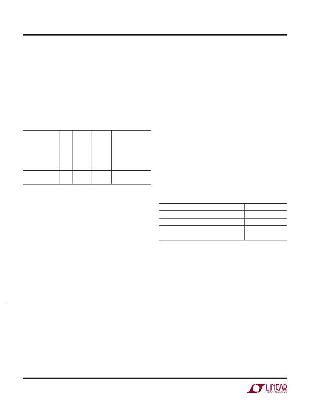
Table 5: Recommended Inductors
Capacitor Selection
The small size and low ESR of ceramic capacitors makes
them suitable for most OLED Driver applications. X5R and
X7R types are recommended because they retain their ca-
pacitance over wider voltage and temperature ranges than
other types such as Y5V or Z5U. A 4.7μF input capacitor
and a 10μF output capacitor are suf?cient for most ap-
plications for the OLED Driver. Always use a capacitor with
a suf?cient voltage rating. Many capacitors rated at 10μF,
particularly 0805 or 0603 case sizes, have greatly reduced
L
MAX
DCR
CURRENT
RATING
capacitance when bias voltages are applied. Be sure to check
actual capacitance at the desired output voltage. Generally
PART
(μH)
( Ω )
(mA) VENDOR
a 1206 size capacitor will be adequate. A 0.47μF capaci-
LQH32CN100K53
LQH2MCN100K02
LQH32CN150K53
LQH2MCN150K02
SD3110-100
SD3110-150
10
10
15
15
10
15
0.3
1.2
0.58
1.6
0.505
0.764
450
225
300
200
470
380
Murata
www.murata.com
Cooper
www.cooperet.com
tor placed on the CAP node is recommended to ?lter the
inductor current while the larger 10μF placed on the V OUT
node will give excellent transient response and stability.
Table 6 shows a list of several capacitor manufacturers.
Consult the manufacturers for more detailed information
Inductor Selection—Boost Regulator
The formula below calculates the appropriate inductor
value to be used for the low noise boost regulator of
the LT3498 (or at least provides a good starting point).
This value provides a good tradeoff in inductor size and
system performance. Pick a standard inductor close to
this value. A larger value can be used to slightly increase
the available output current, but limit it to around twice
the value calculated below, as too large of an inductance
will decrease the output voltage ripple without providing
much additional output current. A smaller value can be
used (especially for systems with output voltages greater
than 12V) to give a smaller physical size. Inductance can
be calculated as:
and for their entire selection of related parts.
Table 6. Recommended Ceramic Capacitor Manufacturers
MANUFACTURER PHONE URL
Taiyo Yuden 408-573-4150 www.t-yuden.com
AVX 843-448-9411 www.avxcorp.com
Murata 814-237-1431 www.murata.com
Kemet 408-986-0424 www.kemet.com
Setting Output Voltage and the Auxiliary
Reference Input
The OLED driver of the LT3498 is equipped with both an
internal 1.215V reference and an auxiliary reference input.
This allows the user to select between using the built-in
reference, and supplying an external reference voltage.
μ H)
The voltage at the CTRL2 pin can be adjusted while the
L = (V OUT2 ? V IN(MIN) + 0.5V) ? 0.66( μ H)
where V OUT2 is the desired output voltage and V IN(MIN)
is the minimum input voltage. Generally, a 10μH or 15μH
inductor is a good choice.
chip is operating to alter the output voltage of the LT3498
for purposes such as display dimming or contrast adjust-
ment. To use the internal 1.215V reference, the CTRL2
pin must be held higher than 1.5V. When the CTRL2 pin
is held between 0V and 1.5V the OLED driver will regulate
the output such that the FB2 pin voltage is nearly equal to
the CTRL2 pin voltage. At CTRL2 voltages close to 1.215V,
3498fa
14
发布紧急采购,3分钟左右您将得到回复。
相关PDF资料
LT3517HUF#PBF
IC LED DRIVER AUTOMOTIVE 16-QFN
LT3519EMS-2#PBF
IC LED DRVR HP CONST CURR 16MSOP
LT3590ESC8#TRMPBF
IC LED DRVR WHITE BCKLGT SC-70-8
LT3591EDDB#TRMPBF
IC LED DRIVER WHITE BCKLGT 8-DFN
LT3593ES6#TRMPBF
IC LED DRIVR WHITE BCKLGT TSOT-6
LT3595AEUHH#TRPBF
IC LED DRIVR WHITE BCKLGT 56-QFN
LT3595EUHH#TRPBF
IC LED DRIVR WHITE BCKLGT 56-QFN
LT3596EUHG#PBF
IC LED DVR 300MA ADJ 52-VQFN
相关代理商/技术参数
LT34-SC
制造商:THOMAS & BETTS 功能描述:
LT3500
制造商:World Products 功能描述:
LT3500EDD#PBF
功能描述:IC REG DL BUCK/LINEAR 12-DFN RoHS:是 类别:集成电路 (IC) >> PMIC - 稳压器 - 线性 + 切换式 系列:- 标准包装:2,500 系列:- 拓扑:降压(降压)同步(3),线性(LDO)(2) 功能:任何功能 输出数:5 频率 - 开关:300kHz 电压/电流 - 输出 1:控制器 电压/电流 - 输出 2:控制器 电压/电流 - 输出 3:控制器 带 LED 驱动器:无 带监控器:无 带序列发生器:是 电源电压:5.6 V ~ 24 V 工作温度:-40°C ~ 85°C 安装类型:* 封装/外壳:* 供应商设备封装:* 包装:*
LT3500EDD#TRPBF
功能描述:IC REG DL BUCK/LINEAR 12-DFN RoHS:是 类别:集成电路 (IC) >> PMIC - 稳压器 - 线性 + 切换式 系列:- 标准包装:2,500 系列:- 拓扑:降压(降压)同步(3),线性(LDO)(2) 功能:任何功能 输出数:5 频率 - 开关:300kHz 电压/电流 - 输出 1:控制器 电压/电流 - 输出 2:控制器 电压/电流 - 输出 3:控制器 带 LED 驱动器:无 带监控器:无 带序列发生器:是 电源电压:5.6 V ~ 24 V 工作温度:-40°C ~ 85°C 安装类型:* 封装/外壳:* 供应商设备封装:* 包装:*
LT3500EDD-PBF
制造商:LINER 制造商全称:Linear Technology 功能描述:Monolithic 2A Step-Down Regulator Plus Linear Regulator/Controller
LT3500EDD-TRPBF
制造商:LINER 制造商全称:Linear Technology 功能描述:Monolithic 2A Step-Down Regulator Plus Linear Regulator/Controller
LT3500EMSE#PBF
功能描述:IC REG DL BUCK/LINEAR 16-MSOP RoHS:是 类别:集成电路 (IC) >> PMIC - 稳压器 - 线性 + 切换式 系列:- 标准包装:2,500 系列:- 拓扑:降压(降压)同步(3),线性(LDO)(2) 功能:任何功能 输出数:5 频率 - 开关:300kHz 电压/电流 - 输出 1:控制器 电压/电流 - 输出 2:控制器 电压/电流 - 输出 3:控制器 带 LED 驱动器:无 带监控器:无 带序列发生器:是 电源电压:5.6 V ~ 24 V 工作温度:-40°C ~ 85°C 安装类型:* 封装/外壳:* 供应商设备封装:* 包装:*
LT3500EMSE#TRPBF
功能描述:IC REG DL BUCK/LINEAR 16-MSOP RoHS:是 类别:集成电路 (IC) >> PMIC - 稳压器 - 线性 + 切换式 系列:- 标准包装:2,500 系列:- 拓扑:降压(降压)同步(3),线性(LDO)(2) 功能:任何功能 输出数:5 频率 - 开关:300kHz 电压/电流 - 输出 1:控制器 电压/电流 - 输出 2:控制器 电压/电流 - 输出 3:控制器 带 LED 驱动器:无 带监控器:无 带序列发生器:是 电源电压:5.6 V ~ 24 V 工作温度:-40°C ~ 85°C 安装类型:* 封装/外壳:* 供应商设备封装:* 包装:*
